From SysML to C++ - The MBSE Workflow from System Model to Embedded Code

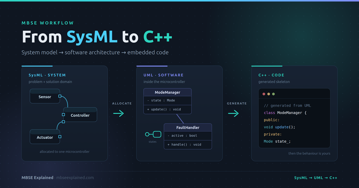 The full chain: SysML for problem and solution domain, UML for the software inside the microcontroller, and generated C++ where it finally becomes code.
Most MBSE presentations end at the same place: a clean architecture diagram, a satisfied nod, and an implicit "…and then the software team implements it." Meanwhile, somewhere down the hall, an embedded developer opens an empty .cpp file and starts typing from scratch — because nothing in that beautiful model told them anything they could actually use.
Welcome to MBSE Explained. That gap is the single biggest credibility problem MBSE has, and it's the one I want to close in this post. I spent nearly five years as a model-based embedded software developer and architect before moving to systems architecture, which means I've stood on both sides of this handoff — and watched it fail from both sides. This is the workflow that actually connects them: SysML for the system, UML for the software, C++ for the target.
Step 1: SysML and the Two Domains
Before anything becomes code, SysML has one job: separate what the problem is from how you intend to solve it. Collapsing those two is the most common modeling mistake I see, and it poisons everything downstream.
The problem domain describes the system's purpose independently of any solution. Stakeholder needs, operational context, the black-box behavior the vehicle or device must exhibit. In SysML that's use cases, activity diagrams, and requirement diagrams. Crucially, nothing here mentions an ECU, a task, or a class. If you can't describe the problem without naming a microcontroller, you've already jumped to a solution.
The solution domain is where you commit. Logical architecture first — functional blocks and their interfaces, still technology-neutral. Then physical architecture — actual ECUs, sensors, buses, and the allocation of logical functions onto them. This is the same layered progression Capella formalizes in Arcadia, and it's the backbone of the V-model workflow most automotive programs already run.
The output that matters for our purposes is narrow and specific: one bounded chunk of functionality, allocated to one microcontroller, with its interfaces, timing, and safety constraints defined. That allocated slice is the contract. Everything after this point is about realizing it in software.
Step 2: The Handoff Boundary — Where SysML Stops and UML Begins
This is the part people get wrong, and it's worth slowing down for, because the boundary is a genuine design decision rather than a rule you can look up.
Teams fail in both directions. Some push SysML down into software detail — modeling classes, methods, and data structures in a systems tool. The model becomes enormous, the systems engineers lose the plot, the software engineers won't touch it, and it rots. Others jump straight to UML as soon as an ECU is named, and lose all traceability back to the system requirements that justified the software's existence in the first place.
The division of responsibility that has worked for me:
- SysML owns what this ECU must do, and why. Allocated requirements, external interfaces, timing and safety constraints, and the traceability back to stakeholder needs.
- UML owns how the software inside that ECU is structured. Classes, components, state behavior, task decomposition.
The boundary artifact is the software requirement set plus interface specification allocated to that microcontroller. That's the thing that crosses the fence. And the single non-negotiable is that traceability must cross it too — every UML component should trace back to an allocated system requirement. If that chain breaks, you no longer have MBSE; you have two unrelated modeling exercises that happen to be about the same product. That traceability discipline is exactly what I covered in requirements traceability in automotive MBSE.
Step 3: UML Software Architecture Inside the Microcontroller
Now you're inside the ECU, and the question changes from "what must this do" to "how is this software organized." Four UML views carry most of the weight in embedded work:
- Class diagrams — the static structure. Components, classes, interfaces, and their relationships. This is the view that will eventually become your C++ headers, so it's worth getting the interfaces honest here.
- State machine diagrams — the behavior that actually matters in embedded systems. Mode management, startup and shutdown sequences, fault handling and degraded modes. If your device has a "limp home" state, this is where it lives.
- Sequence diagrams — interaction between components and tasks, especially across asynchronous boundaries. Invaluable for pinning down who calls whom, in what order, and what happens when a message is late.
- Component and deployment views — mapping software components onto tasks, threads, and scheduling, plus memory and resource allocation.
One practical discipline: model at architecture granularity, not implementation granularity. The moment you start modeling every getter and setter, the model costs more to maintain than the code it describes, and it will be abandoned within two sprints. Model the structure, the interfaces, and the behavior that's hard to reason about in your head. Let the compiler handle the rest.
A note on approach: whether you decompose functionally or object-orientedly genuinely changes what this layer looks like — I dug into that trade-off in functional vs. object-oriented MBSE. For a C++ target, object-oriented decomposition maps more naturally, which is part of why this workflow hangs together.
Step 4: Generating the C++ Skeleton
Here's where the model finally becomes text you can compile.
StarUML with its C++ extension takes your class diagram and generates C++ skeleton source — headers and implementation stubs with the classes, attributes, operations, and inheritance relationships already in place. You then fill in the behavior.
Be clear-eyed about what that is and isn't. StarUML performs structural generation. It gives you the skeleton; it does not generate behavioral code from your state machines. That distinction matters, because it sets expectations for what the model buys you: consistent structure and interfaces that match the architecture, not a working application.
If you want behavior generated too, that's a different tier of tooling:
- IBM Engineering Systems Design Rhapsody generates executable code from UML state machines, including full behavioral implementation — the heavyweight option, and genuinely capable.
- Simulink with Embedded Coder owns the control-algorithm half of the problem: closed-loop control, signal processing, anything continuous. I covered that toolchain in the MathWorks MBSE workflow post.
- Eclipse Papyrus is the open-source route for UML and SysML together, if licensing is a constraint — one of several options from my open source MBSE tools guide.
A realistic embedded project often uses two of these at once: Simulink-generated control code for the algorithms, and UML-derived structural code for the application and mode-management layers around them.
Step 5: The Second Iteration — The Part Nobody Talks About
Generating a skeleton once is easy. Every tool demo shows exactly that, and it always looks great.
Then the architecture changes. Meanwhile, the developer has written three hundred lines of real logic into those stubs. Regenerate naively and you destroy their work. Don't regenerate, and the model becomes a historical document that describes a system that no longer exists. This is where model-driven embedded projects actually die — not at generation, but at synchronization.
You get three honest strategies, and you must pick one deliberately:
- Generate once, then own the code. The model seeds the project and then becomes documentation. Cheap, and completely fine if you admit that's the deal. The failure mode is pretending the model is still authoritative six months later.
- Protected regions. The generator preserves marked blocks of hand-written code across regenerations. This works, and it's the common middle ground — but the markers are brittle, merges get unpleasant, and refactoring across the boundary is painful.
- Full generation. The model is the single source of truth and code is a build artifact nobody edits by hand. The highest discipline and the highest payoff — architecture changes propagate automatically — but it demands mature tooling (Rhapsody-class) and a team genuinely willing to stop editing generated files.
Whichever you choose, enforce it in CI. Regenerate from the model in the pipeline and fail the build on unexpected diffs. A sync strategy that lives only in a wiki page is a sync strategy that has already failed.
The Automotive Reality Check
Three constraints that will shape this workflow in a real program:
MISRA C++ compliance. Generated code is still code, and it still has to pass your coding standard. Generators are not automatically MISRA-clean — check what your generator emits before you commit to it, not during your first static-analysis run.
ISO 26262 tool qualification. If generated code ends up in a safety-relevant path, your code generator becomes a tool requiring confidence assessment and potentially qualification. That's a real cost, and it's a strong argument for using a qualified commercial generator rather than a community extension on anything ASIL-rated.
Where C++ actually fits. Classic AUTOSAR is a C world — this workflow is not aimed there. It fits Adaptive AUTOSAR (C++14 and later), higher-compute ECUs, and non-AUTOSAR embedded products like ODM IoT hardware, where you control the whole stack. Being honest about that boundary is better than promising a workflow that won't survive contact with a Classic ECU.
What Good Looks Like
Pulling the chain together: stakeholder needs and black-box behavior in SysML's problem domain; logical then physical architecture in the solution domain, ending with functionality allocated to a specific microcontroller; a clean handoff artifact of software requirements plus interfaces, with traceability crossing the boundary; UML class, state, sequence, and deployment views at architecture granularity inside the ECU; C++ skeletons generated from the structural model; and a consciously chosen, CI-enforced synchronization strategy holding it all together over time.
None of this requires a heroic toolchain. It requires deciding where each model's authority begins and ends — and then being disciplined enough not to blur those lines when a deadline arrives.
That's the mission here at MBSE Explained — simplifying systems for smarter EVs. Where does this chain break in your organization: the SysML-to-UML handoff, or keeping the model and the code in sync afterwards? I'd genuinely like to know in the comments — it's the question I get asked most.